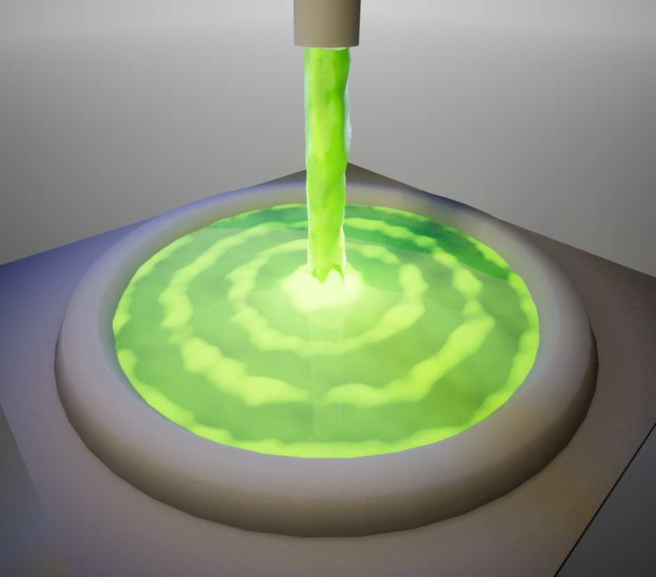
The Inspiration
I was checking out a really well made YouTube channel about Technical Art – Burkhardt Design – and in particular this video, in which the author creates a noise-based material for a waterfall. I really liked the look of it, and I tried to create my own version.
The result is a small piece combining a little bit of Materials, Dynamic Meshes and Modeling, for a stinky/toxic look!
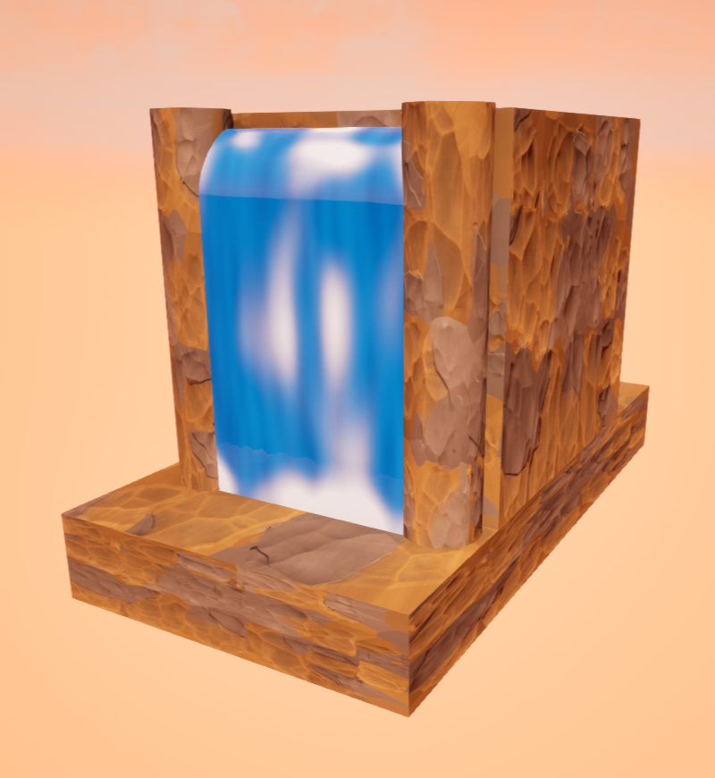
Right away, I thought about using the foam mask to displace the mesh, and add depth to the material. This step required the creation of a material with a sufficient number of vertices. Since I did not know what kind of detail I was aiming for, nor the shape I wanted to settle on, I experimented a bit with mesh generation within Unreal.
Eventually, I decided to try a material sharing some ideas with the waterfall one, but which could on a cylindrical shape. A vertical pipe regurgitating some slimey waste onto a puddle seemed like a good fit for this:
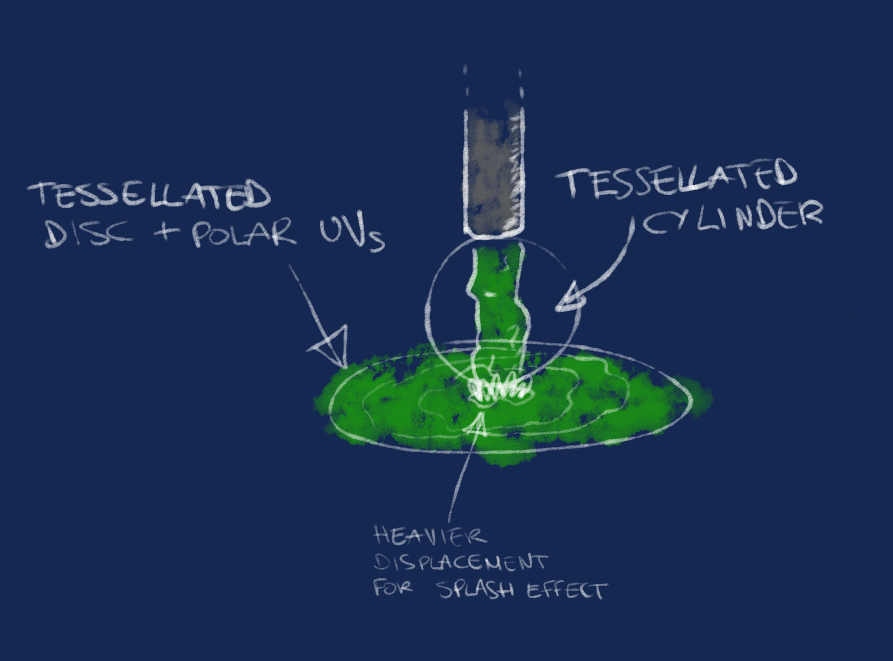
As the image shows, the design consists of 2 main meshes: a cylinder and a disc. Both needed quite a bit of tessellation, since I wanted to play with vertex displacement.
The Flowing Liquid
Flowing Liquid Mesh (a cylinder, really)
The mesh used for the main liquid flow is made procedurally using Dynamic Mesh Components. I opted for a C++ custom component which allows to customize a few parameters within the editor. It is not particularly refined, but it has basic support for some undo transactions, and updates when properties are changed in the details panel.
Having a dynamic mesh allowed to experiment with the detail level and iterate quickly.
Dynamic Mesh Cylinder source code
Below, the header and source files for the dynamic mesh cylinder.
// Dario Mazzanti

#pragma once

#include "Components/DynamicMeshComponent.h"
#include "CylinderDynamicMeshComponent.generated.h"

struct FPropertyChangedEvent;

UCLASS(MinimalAPI)
class UCylinderDynamicMeshComponent : public UDynamicMeshComponent
{
	GENERATED_BODY()

public:
	UCylinderDynamicMeshComponent();

	//~ Begin UActorComponent
	virtual void InitializeComponent() override;
	//~ End UActorComponent

	//~ Begin UObject
	virtual void PostEditChangeProperty(FPropertyChangedEvent& PropertyChangedEvent) override;
	virtual void PostLoad() override;
	virtual void PostTransacted(const FTransactionObjectEvent& InTransactionEvent) override;
	//~ End UObject

	UPROPERTY(EditAnywhere, BlueprintReadWrite, Category = "Dynamic Cylinder")
	float Radius = 20.0f;

	UPROPERTY(EditAnywhere, BlueprintReadWrite, Category = "Dynamic Cylinder")
	float Height = 200.0f;

	UPROPERTY(EditAnywhere, BlueprintReadWrite, Category = "Dynamic Cylinder")
	int HeightDetail = 20;

	UPROPERTY(EditAnywhere, BlueprintReadWrite, Category = "Dynamic Cylinder")
	int RadialDetail = 32;

	UPROPERTY(EditAnywhere, BlueprintReadWrite, Category = "Dynamic Cylinder")
	TSoftObjectPtr<UMaterialInterface> CylinderMaterial;

protected:
	void BuildCylinder();
	void ApplyMaterial();

	UPROPERTY(Transient)
	TObjectPtr<UMaterialInstance> MaterialInstance;
};
// Dario Mazzanti


#include "CylinderDynamicMeshComponent.h"
#include "Generators/SweepGenerator.h"

namespace DynamicCylinder
{
	static const FName RadiusPropertyName = GET_MEMBER_NAME_CHECKED(UCylinderDynamicMeshComponent, Radius);
	static const FName HeightPropertyName = GET_MEMBER_NAME_CHECKED(UCylinderDynamicMeshComponent, Height);
	static const FName HeightDetailPropertyName = GET_MEMBER_NAME_CHECKED(UCylinderDynamicMeshComponent, HeightDetail);
	static const FName RadialDetailPropertyName = GET_MEMBER_NAME_CHECKED(UCylinderDynamicMeshComponent, RadialDetail);
	static const FName MaterialPropertyName = GET_MEMBER_NAME_CHECKED(UCylinderDynamicMeshComponent, CylinderMaterial);

	TSet<FName> CylinderGeometryProperties = {RadiusPropertyName, HeightPropertyName, HeightDetailPropertyName, RadialDetailPropertyName};
}

// Sets default values for this component's properties
UCylinderDynamicMeshComponent::UCylinderDynamicMeshComponent()
{
	PrimaryComponentTick.bCanEverTick = false;
}

void UCylinderDynamicMeshComponent::BuildCylinder()
{
	EditMesh([&](FDynamicMesh3& OutMesh)
	{
		OutMesh.Clear();

		UE::Geometry::FCylinderGenerator CylinderGenerator;
		CylinderGenerator.Radius[0] = FMath::Max(FMathf::ZeroTolerance, Radius);
		CylinderGenerator.Radius[1] = FMath::Max(FMathf::ZeroTolerance, Radius);
		CylinderGenerator.Height = FMath::Max(FMathf::ZeroTolerance, Height);
		CylinderGenerator.LengthSamples = HeightDetail;
		CylinderGenerator.AngleSamples = RadialDetail;
		CylinderGenerator.bCapped = true;
		CylinderGenerator.bPolygroupPerQuad = false;
		CylinderGenerator.Generate();

		OutMesh.Copy(&CylinderGenerator);
	});
}

void UCylinderDynamicMeshComponent::ApplyMaterial()
{
	if (!CylinderMaterial.IsValid())
	{
		return;
	}

	if (!MaterialInstance)
	{
		MaterialInstance = UMaterialInstanceDynamic::Create(CylinderMaterial.Get(), this);
	}

	SetMaterial(0, MaterialInstance);
}

void UCylinderDynamicMeshComponent::InitializeComponent()
{
	Super::InitializeComponent();
	BuildCylinder();
}

void UCylinderDynamicMeshComponent::PostEditChangeProperty(struct FPropertyChangedEvent& PropertyChangedEvent)
{
	Super::PostEditChangeProperty(PropertyChangedEvent);

	const FName ChangedPropertyName = PropertyChangedEvent.GetMemberPropertyName();

	if (DynamicCylinder::CylinderGeometryProperties.Contains(ChangedPropertyName))
	{
		BuildCylinder();
	}
	else if (ChangedPropertyName == DynamicCylinder::MaterialPropertyName)
	{
		ApplyMaterial();
	}
}

void UCylinderDynamicMeshComponent::PostLoad()
{
	Super::PostLoad();
	BuildCylinder();
}

void UCylinderDynamicMeshComponent::PostTransacted(const FTransactionObjectEvent& InTransactionEvent)
{
	Super::PostTransacted(InTransactionEvent);

	if (InTransactionEvent.HasPropertyChanges() && InTransactionEvent.GetEventType() == ETransactionObjectEventType::UndoRedo)
	{
		const TArray<FName>& ChangedProperties = InTransactionEvent.GetChangedProperties();

		for (const FName PropertyName : DynamicCylinder::CylinderGeometryProperties)
		{
			if (ChangedProperties.Contains(PropertyName))
			{
				BuildCylinder();
				ApplyMaterial();
				break;
			}
		}

		if (ChangedProperties.Contains(DynamicCylinder::MaterialPropertyName))
		{
			ApplyMaterial();
		}
	}
}
Flowing Liquid Material
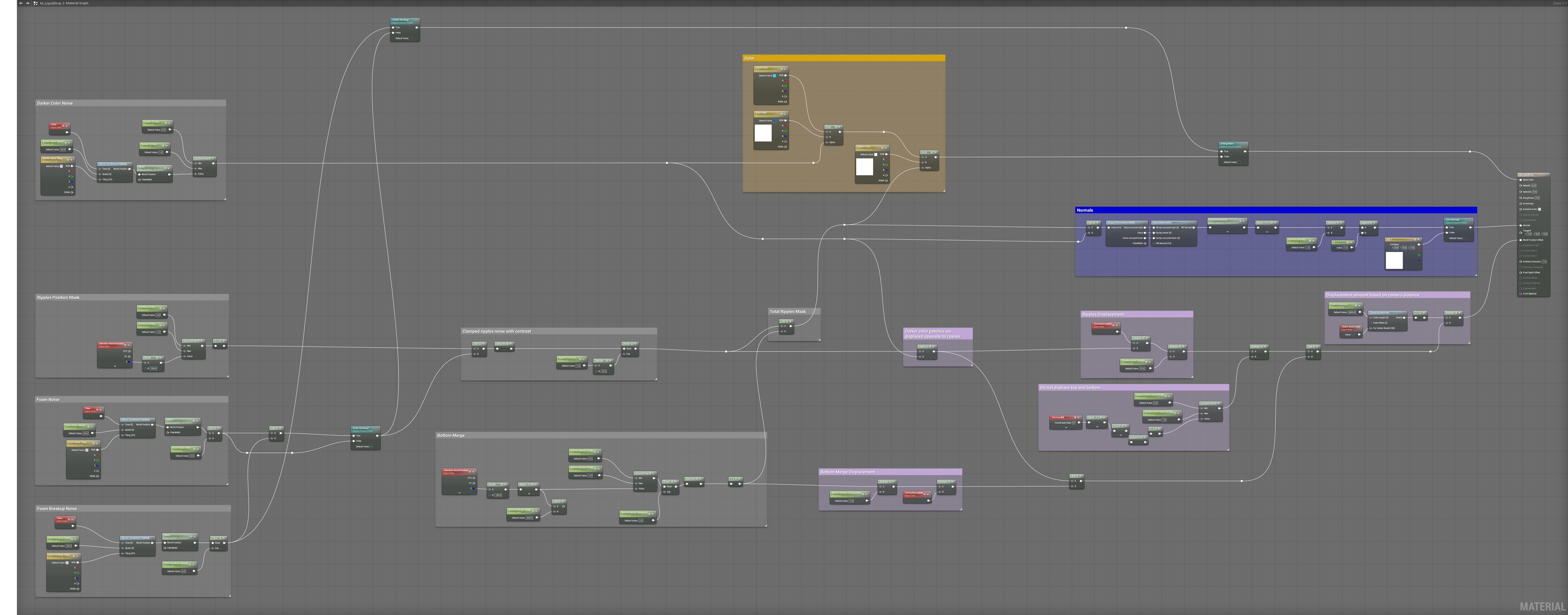
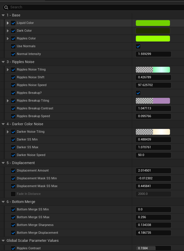
The cylinder material mainly acts through Noise-based Masks on Color, Normals and Vertex Displacement.
There is a mask to generate darker areas, one for ripples, and one to add further ripple details. This is quite similar to what was done by the original waterfall material.
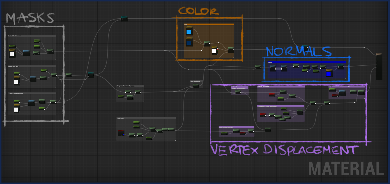
Masks pattern
Noise-based Masks all work with the same pattern shown in the referenced video: leveraging world space coordinates and the Noise material node, which is initialized at different scale and values. Noise is tiled using a Vector3 parameter, and a speed parameter allows to determine at which speed the detail given by the noise moves. This essentially makes the liquid “flow”.
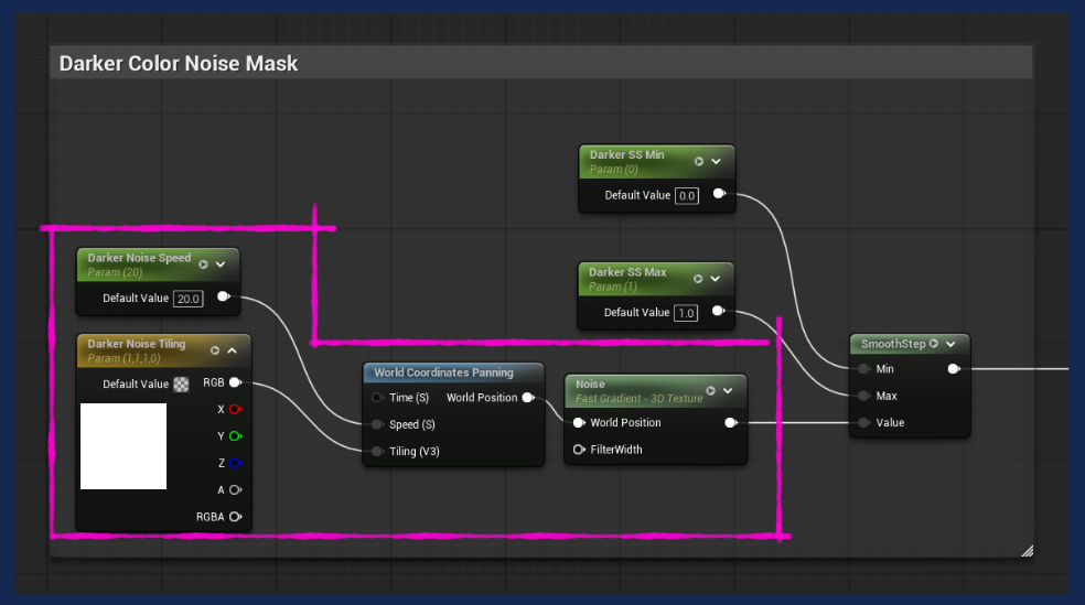
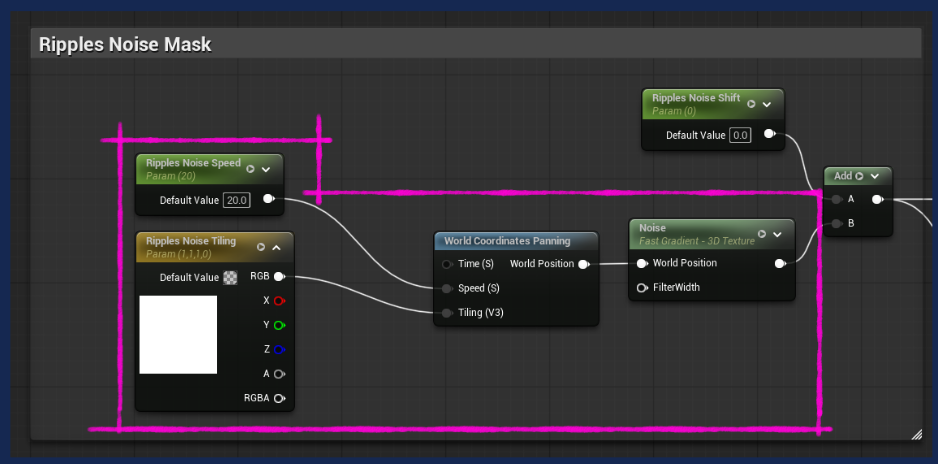
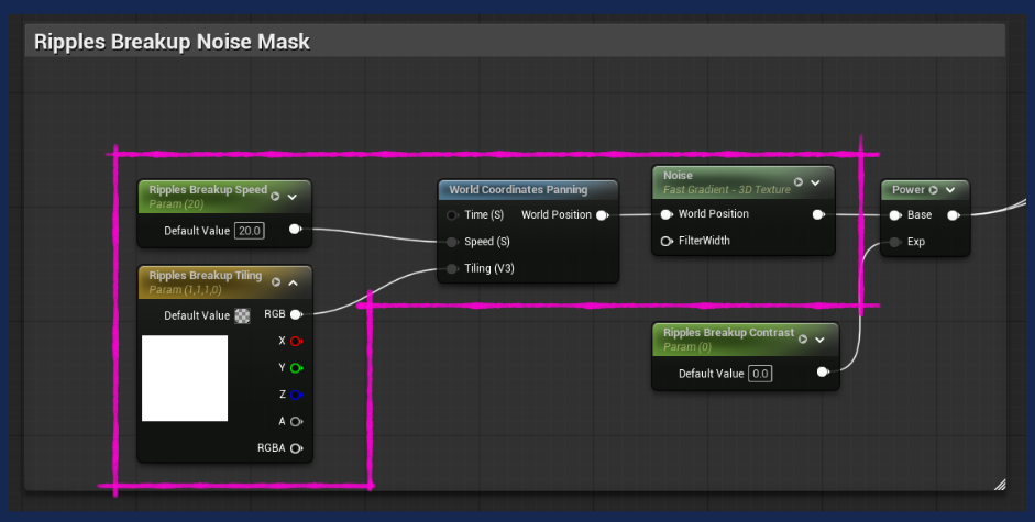
To avoid repeating the same graph nodes for Tiling and Panning, I created a custom material function, which is used by all noise masks:
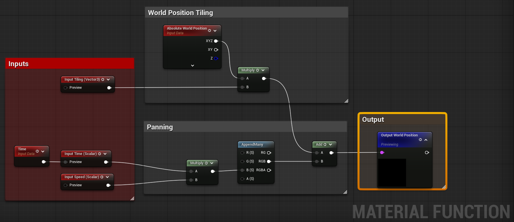
The 3 masks are combined in different ways, and used to create interesting effects on the Material. As the original waterfall Material did, it is possible to enable or disable additional ripples.
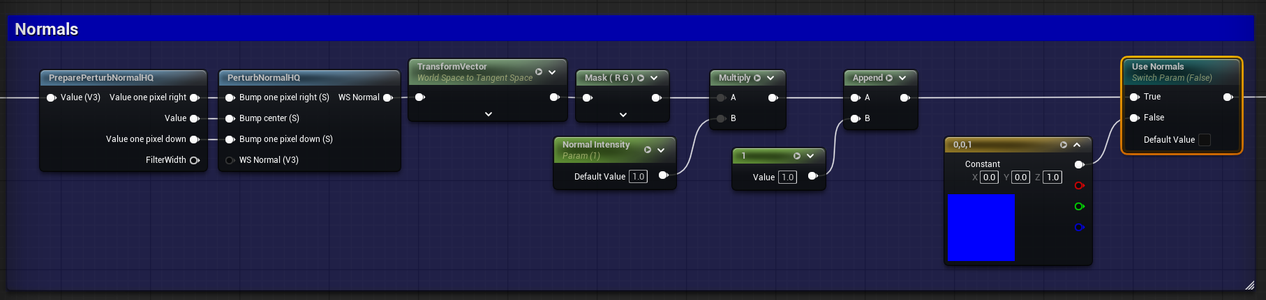
Masks are also used for Normals generation, as shown here:
Displacement
The ripples and darker color masks are combined so that ripples are displaced “outwards” along the normal direction, while the darker areas are displaced “inwards”.
Additionaly, there is a mask dedicated to avoid displacement to happen at the top and bottom of the cylinder, and another one to optionally make the bottom of the cylinder larger. The latter is a property which could be used to merge with the upcoming puddle mesh.
Finally, the displacement amount is reduced as the distance from the camera increases. Not stricly necessary – an alternative solution would be to have a material with no vertex displacement, dedicated to a LOD mesh used when the camera is far from the object.
The Puddle
Puddle Disc Mesh
Different from the cylinder, the disc mesh was done in Blender. It’s a disc with a significant amount of vertices, and polar UVs. The V channel increases from the center of the mesh (0) to its edge (1). This step helps creating ripples in a straightforward way.
Puddle Material
The approach used to create the puddle material is similar to what we’ve seen for the cylinder. We’ve got tiled and panned noise used to create variations on mathematically generated masks. In particular, there is a mask dedicated to concentrical ripples, and one dedicated to the splash which would be generated by liquid falling at the center of the puddle.
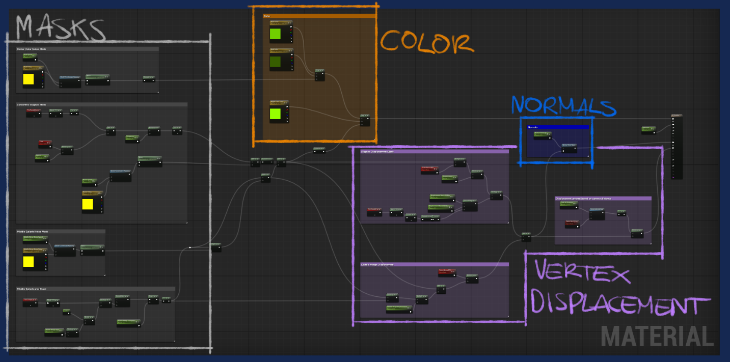
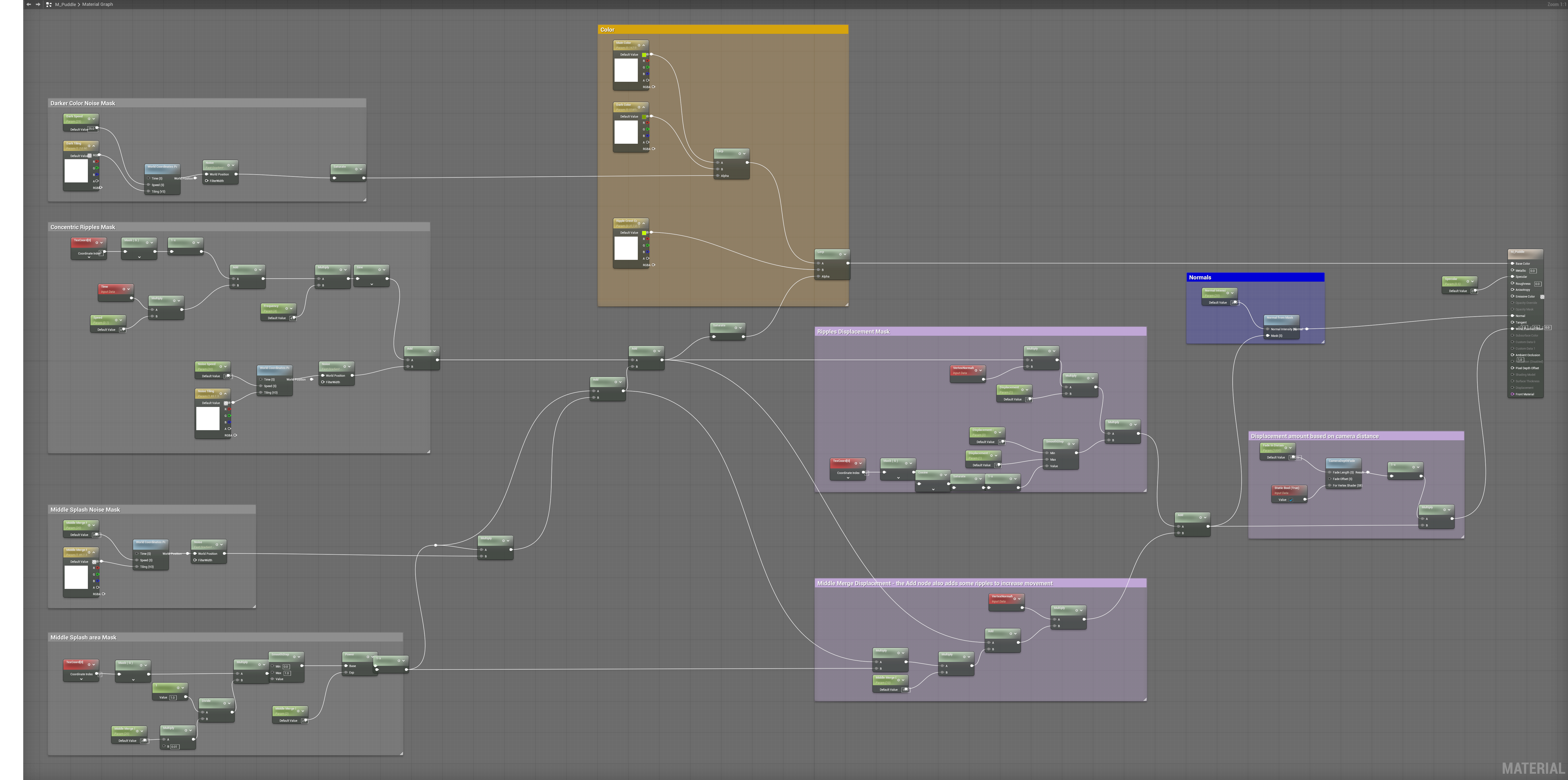
Masks, Displacement and other details
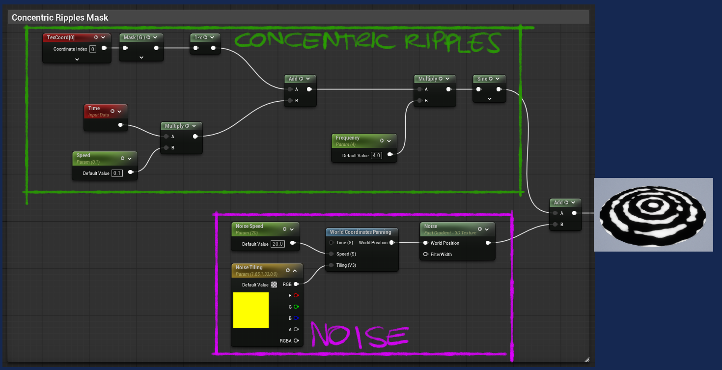
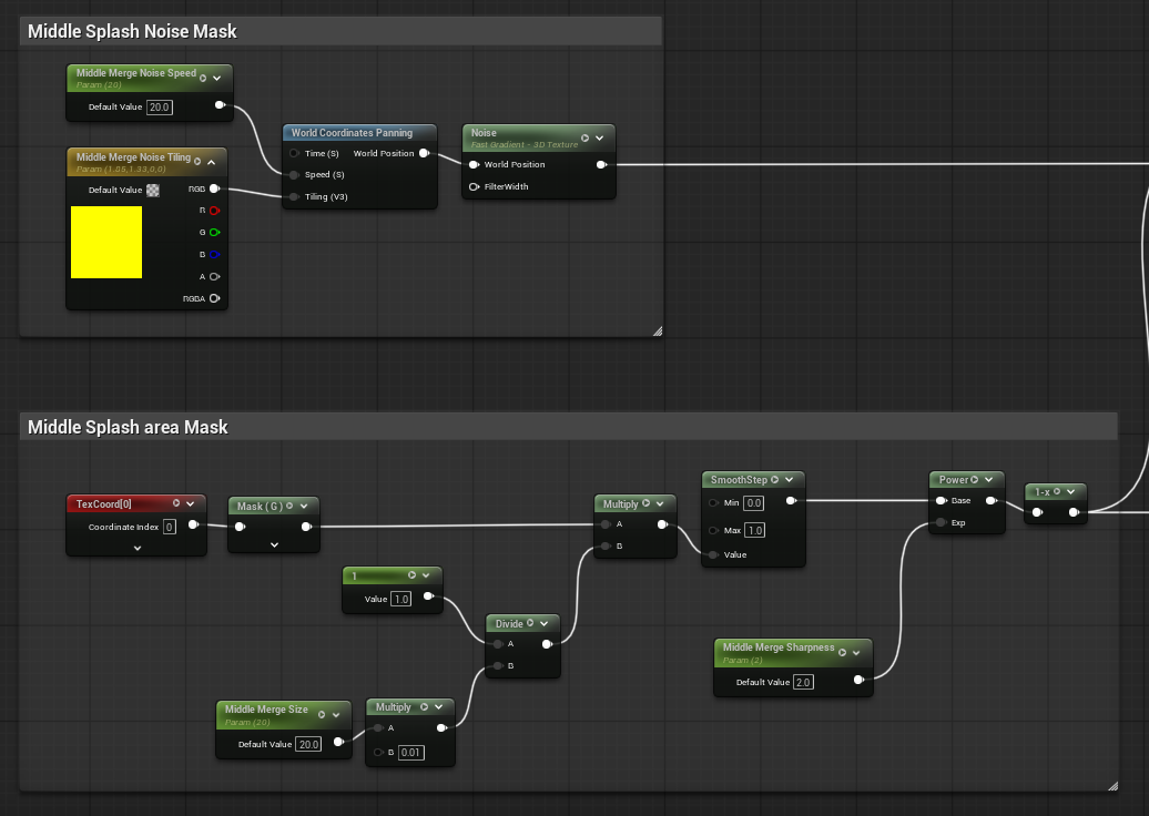
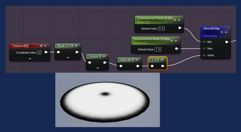
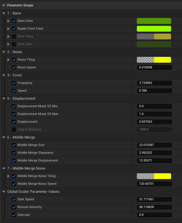
The middle splash mask is used both for coloring and for displacement. The color works better if it matches the ripple color from the cylinder material. Regarding the displacement: it is really helpful to hide the connection point between the 2 meshes.
The edge would in fact be quite visible, despite both meshes having the same color, since the noise masks used to create ripples will not match between the meshes. This is particularly true because all cylinder mesh noise works with world based coordinates, while the puddle only uses world based noise for variety, with concentric ripples and splash mask being UV-based.
Additionally to the ripples and splash displacement logic, there are masks dedicated to tweak the displacement amount at the center and edge of the disc mesh.
Note: the Normals are generated in the same way they are generated by the cylinder material. Here the logic is wrapped in a custom material.
Some Thoughts
This is definitely a “study piece”, which should be likely modified and adapted to be properly used in a production environment.
Using so many vertices could be reasonable for a central environment piece. I would probably not use a dynamically generated mesh for that, but bake it once happy with the detail level, or model one.
For other uses, for example a small part of an environment, maybe used in different areas, I would ditch the vertex displacement and just handle things with color and our mask-generated normals.
In that case, I would probably try to make a better use of world position based noise, so that the separate meshes don’t have a visible edge in their contact area. The other advantage of world position based materials is that it is possible to use them on scaled meshes – which could be good for reusability.
Some decals with caustic-reflection like effects could be used, or some particle effects.
Within a proper context, we could imagine some masks used by the pipe and other materials surrounding the puddle to add splashes and dirt caused by the liquid, or even some steam-like effects.
Final Result
Here’s the final result. I added a point light at the center of the puddle, and a post process with a bloom and vignette effects to highlight the piece.
Thanks for reading!